


Indoor/Outdoor FTTH cable
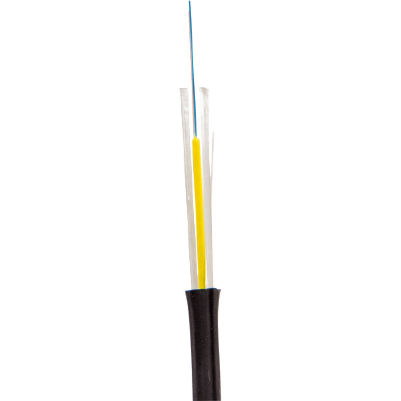
Used as a distribution cable for suspension on the utility poles, electricity pylons, between buildings, and for cabling inside buildings, in cable ducts, pipes, also for outdoor cabling along the external facades of buildings.
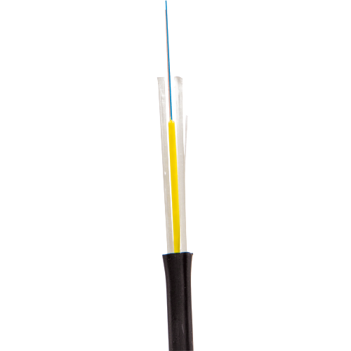
The cable has an optical module with loose fibers. The free space in the optical module is filled with a hydrophobic gel. Two FBR rods are used as strength members. The optical module and strength members are covered with a jacket made of a flame retardant, halogen-free, low-smoke polymer composition.
Cable jacket color is black.
The maximum possible count of optical fibers in the cable is 8.
Design

Color identification of optical fibers:
| № | Fibers 1-8 |
| 1 | Blue |
| 2 | Orange |
| 3 | Green |
| 4 | Brown |
| 5 | Grey |
| 6 | White |
| 7 | Red |
| 8 | Black |
Weight and dimensions
Fiber count in the cable | Up to 4 | From 6 to 8 |
Cable dimensions, mm | 2,0 x 4,4 | 2,4 x 5,6 |
Cable weight, kg/km | 13,3 | 20,5 |
Operating conditions
Operating Temperature | -50°C…+70°C |
Installation Temperature | -10°C…+50°C |
Storage Temperature | -50°C…+50°C |
Minimum Bend Radius | At least 10 cable diameters |
Lifetime | 25 years |
Physical specifications
Optical cable is resistant to the following impacts
Impact type | Nominal value | Criteria for evaluation |
|---|---|---|
Installation pulling tension (IEC 794-1-93 E1 test procedure) | 400 N (up to 4 fibers) | Δα* ≤ 0,05 dB no damage |
Crush resistance | 1 kN/cm | |
Dynamic bending stresses | 20 cycles at an angle ±90° | |
Axial twisting stresses | 10 cycles at an angle of ± 360 ° at a length of 4 m | |
Impact (IEC 794-1-93 E4 test procedure) | Impact energy is 1 J | |
Climatic impact* | Temperature range from | Δα ≤ 0,05 dB/km |
* - increase in attenuation of an optical fiber in a cable at specific wavelengths.
Applicable optical fibers
SU | Single-mode fiber with extended operating wavelength and reduced attenuation and low bending loss (ITU G.652D+G.657.A1 recommendation) |
S2 | Single-mode fiber with an extended bandwidth of operating wavelengths (ITU-T G.652D recommendation) |
S5 | Single-mode positive non-zero dispersion shifted fiber (ITU-T G.655 recommendation) |
S7 | Single-mode with low bending loss (ITU-T G.657 recommendation) |
M1 | Multi-mode with core to cladding ratio 62,5/125 μm (IEC 60793-2-10 A1b type recommendation) |
M2 | Multi-mode with core to cladding ratio 50/125 μm (ITU-T G.651 recommendation and IEC 60793-2-10 type A1a.1 requirements) |
M3 | Multi-mode with low bending loss and core to cladding ratio 50/125 μm (ITU-T G.651 recommendation and IEC 60793-2-10 A1a.2 type requirements) |
M4 | Single-mode fiber with extended operating wavelength and reduced attenuation and low bending loss (ITU G.652D+G.657.A1 recommendation) |
Frequently Asked Questions
What is the LAN-OFC-FUMFx-yy-HF cable used for?
Universal FTTH (Fiber To The Home) optical cable with an optical module containing loosely laid fibers; the maximum fiber count is 8. Two fiberglass rods act as strength members, and the black jacket does not propagate flame, is halogen-free and has low smoke.
Where can this cable be installed?
The cable is suitable for aerial installation on communication and power-line poles, lighting poles and between buildings and structures, as well as for installation inside buildings, on facades, in trays, ducts, cable ducts, pipes, blocks and tunnels.
How is the part number decoded and which versions are in the series?
In LAN-OFC-FUMFx-yy-HF, x is the fiber count, yy is the fiber type and HF (Halogen Free) is the nг(А)-HF jacket. The series includes versions with 2, 4 fibers. Fiber types: SU — G.652D single-mode fiber with low bend loss (G.657.A1). Jacket: HF — nг(А)-HF jacket: does not propagate flame in bunched installation (category A), halogen-free, low smoke. Choose the version by fiber count, fiber type and installation conditions.
What temperatures and forces are permitted during installation and operation?
Operating temperature is −50 to +70 °C and installation temperature is −10 to +50 °C. The permitted tensile force is 400 N for cables with up to 4 fibers and 700 N for 6–8 fibers.
What is the minimum bend radius of the cable?
The minimum bend radius is at least 10 cable diameters. Watch the bend radius during installation and in the closure.
How are fibers identified by color?
Fibers are identified by color code: 1 — blue, 2 — orange, 3 — green, 4 — brown, 5 — gray, 6 — white, 7 — red, 8 — black, 9 — yellow, 10 — violet, 11 — pink, 12 — turquoise (aqua). From fiber 13 onward the same colors are used with an additional mark or ring.
What should I do with the hydrophobic gel when preparing the cable?
The free space in the optical module and under the armor is filled with hydrophobic gel. Before termination, remove the gel from the fibers with special lint-free wipes and a cleaner recommended by the splicing equipment manufacturer, and only then strip the fiber coating and cleave. Gel on the fiber impairs cleaving, splicing and cleaning.
What tools prepare the cable and how are the fibers terminated?
Remove the cable jacket without damaging the optical module and open the module. Secure the strength members (fiberglass rods) in the frame or closure. Then strip the 900 µm buffer and 250 µm acrylate coating from the fiber with a stripper such as LAN-FT-STR/OFC, clean the fiber and cleave it. Fibers are terminated with pigtails (fusion splice or the LAN-FMS mechanical splice) or with field-installable connectors.