


Finger section, 4U, universal, 106 mm depth
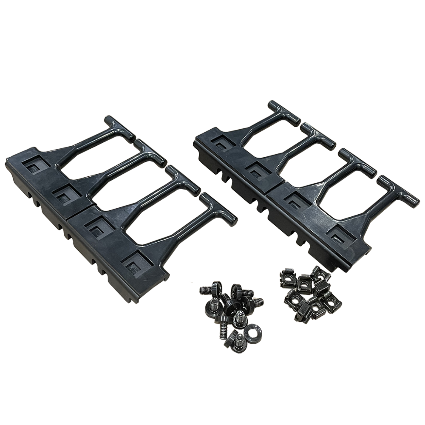
The vertical cable management section is designed to distribute cable flows in various mounting structures.
The cables are distributed by "fingers" arranged in 1U increments. The elements are made of reinforced plastic and support the cables at the level of each unit. The rounded surface of the "fingers" protects the cable jacket from damage and provides the required bending radius.
The section is mounted on rails with cage nuts and screws in the appropriate holes, in conjunction with the equipment or patch panels. This method of mounting makes the cable manager universal, it can be installed on any regular rails in cabinets of any height.
The cable managers are available with a plastic fingers 106 mm depth.
The package includes two cable manager sections and the necessary fixtures for installation.
Made of steel and reinforced plastic
Color is black (RAL 9005).
Frequently asked questions and answers
What is the LAN-DC-CB-4U-PF/S cable comb designed for?
This universal 4U vertical cable comb distributes cable runs next to equipment or patch panels and is compatible with standard rails in cabinets of any height.
How is the comb mounted in the cabinet?
The comb mounts to the rails with captive nuts in the matching holes.
How deep are the comb's fingers?
The finger depth is 106 mm.
What material is the comb made of, and does it protect the cable from damage?
The comb is made of steel and reinforced black plastic (RAL 9005); the rounded finger surfaces protect the cable jacket and maintain the allowed bend radius.
How many combs come in one package?
The package includes 2 combs and the mounting hardware needed for installation.
Assembly Instructions
Finger section, 4U, universal, 106 mm depth LAN-DC-CB-4U-PF/S
-
Prepare the kit and mounting position
Check that the kit contains two cable finger brackets and the mounting hardware. Have a screwdriver ready. Choose a position beside the patch panels for vertical cable routing. Allow for the 4U bracket height and 106 mm finger depth.
-
Loosely fit the patch panel
Fit cage nuts into the rail holes at the required height. Support the patch panel and loosely fit its screws, leaving space to slide the cable finger bracket beneath the panel mounting bracket.
-
Fit the cable finger bracket beneath the panel bracket
Slide the mounting part of the finger bracket beneath the patch panel bracket. Align the mounting holes and position the fingers beside the panel to guide the cables along the rail.
-
Align and tighten the fasteners
Align the panel and cable finger bracket. Tighten the screws in the cage nuts and check that both parts are firmly secured to the rail.
-
Fit the adjacent panel and second finger bracket
If required, fit the adjacent panel and the finger bracket on the opposite side in the same way. The example shows two panels stacked vertically, with finger brackets guiding the cables on both sides.
-
Route the patch cords
Connect the patch cords to the panel and guide them to the required side through the spaces between the fingers. Distribute the cords without tension or pressure on the connectors.
-
Check the patch cord distribution
Check that the cords are not taut or sharply bent and that the connectors are free of strain. The rounded fingers support the cords at 1U intervals. Observe the minimum bend radius specified for each cable.
Package dimensions and weight
Single item
| Product code | Unit | length × width × height (mm) | Weight (kg) | Volume (m3) |
|---|---|---|---|---|
| LAN-DC-CB-4U-PF/S | pcs | 190 × 110 × 20 | 0.28 | 0.000418 |